Theatrone Data
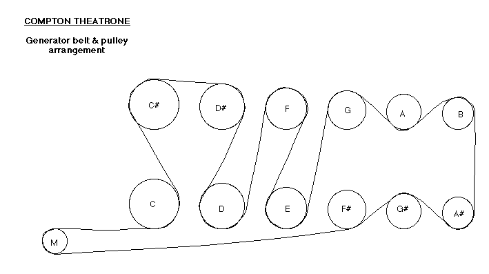
Pulley & Belt Arrangement

Made-to-measure belting suppliers: A.C. Belting
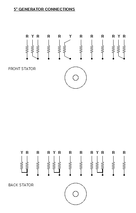
Stator Wiring
Front is nearest the pulleys
'R' indicates organ voices wiring
'Y' indicated Melotone wiring
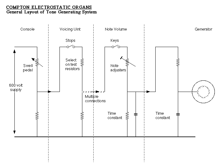
General Diagram of Signal Path
Signal Path (excluding Melotone Unit)
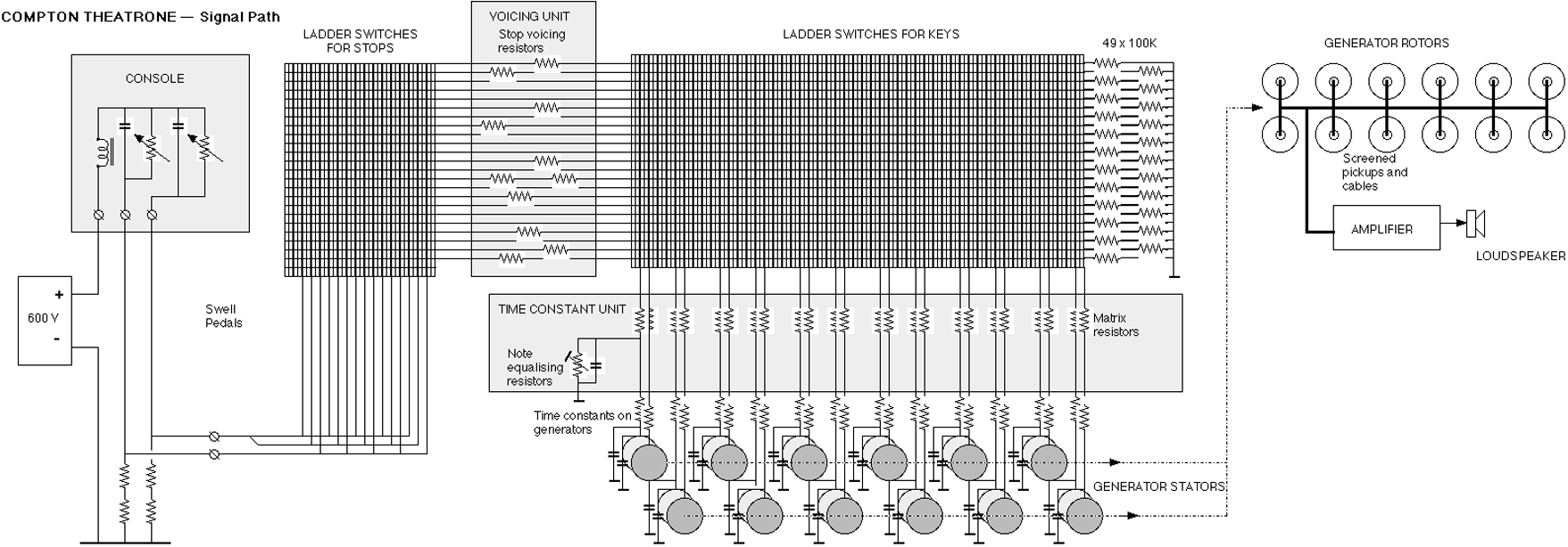
Note: The choke and capacitors in the swell pedal unit appear to be intended as radio interference suppressors, they do not affect the operation of the circuit.
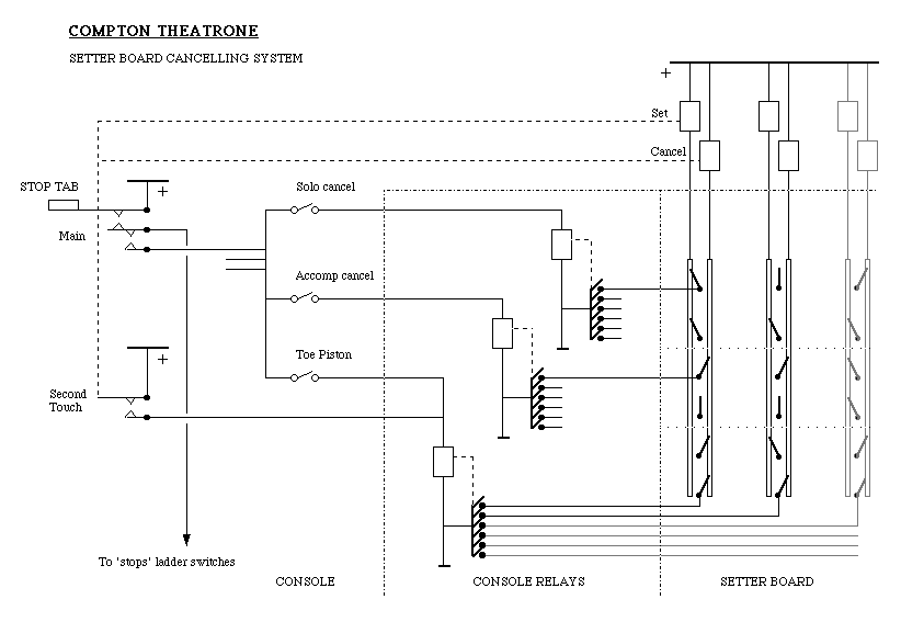
Setter Board Circuit for stops and second-touch
cancel
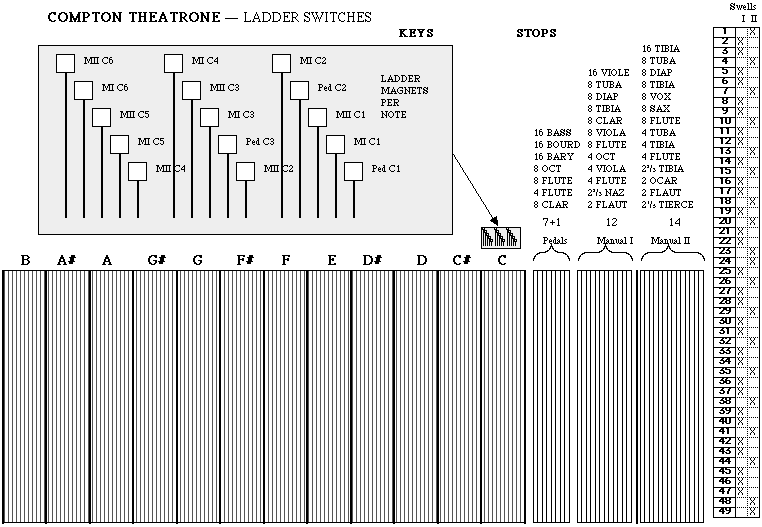
Ladder Relay Layout
Adjusting the tremulant depth
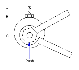 The tremulant crank
To adjust the tremulant depth, make sure the organ is unplugged so that the motor cannot be started by mistake. Rotate the tremulant pulley until the crank takes up the position shown above, with the stop screw 'A' at the top. Loosen locknut 'B' with a 2BA spanner. Loosen crank nut 'C' no more than half a turn with a tubular spanner or large nut-driver (RS Components pot-nut runner tool 438-4239).
Push firmly upwards on the crank nut 'C' and adjust screw 'A' as follows:
To increase tremulant depth, screw 'A' downwards
To decrease tremulant depth, screw 'A' upwards
Make this adjustment a few turns at a time; if 'A' is screwed too far upwards, the crank may go over-centre and the action of the adjusting screw will be reversed. When the adjustment has been made, tighten the locknut 'B' without altering the position of screw 'A'. Then tighten crank nut 'C' whilst continuing to push it firmly upwards.
Repeat the process until a satisfactory result is obtained. If the adjustment does not appear to be occurring in a consistent manner, this is either because 'C' was not being pushed firmly against 'A' when it was being tightened or because the adjustment has taken the crank nut above the centre line of the shaft..