A 6dB per octave slope is generated by a simple R/C
network, if the value of the capacitor is accurately known
and a 10-turn potentiometer used as the resistor, a
turns-counting dial on the resistor shaft can be arranged to
read out the time constant of the R/C network in
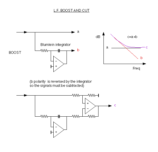
microseconds. By combining this 6dB per octave slope with
the original signal, a 'Blumlein' type of equalisation curve
can be produced. The signal polarity is inverted by the
integrator, so it must either be re-inverted to add it to
the original signal, or it can be subtracted as shown in the
circuit below.
Switching is arranged so that the same time constant
components and their associated amplifiers can perform
either boost or cut functions or pass the signal unaltered.
In practice, the 6dB per octave slope either cannot
extend to infinity or is required not to do so; adjustable
resistor networks associated with the time constant
capacitors are used to set limits to the ranges of the
slopes.
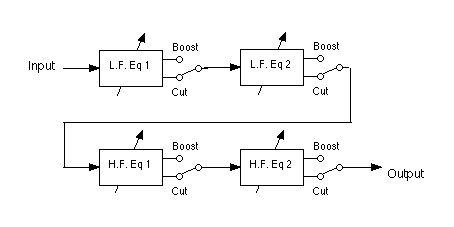
Any stage can be switched to either boost or cut the
relevant band of frequencies at a fixed rate of 6dB per
octave.
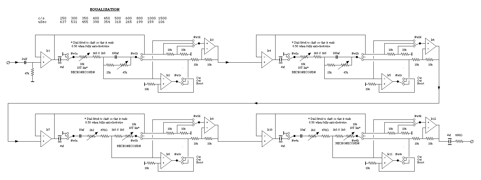
|
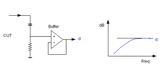
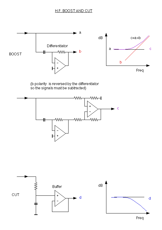
Using the circuit around Ic 1, Ic 2 and Ic 3 as an example: In the 'Boost' position of the switch, Ic 1 acts as a untiy-gain buffer, Ic 2 is arranged as the Blumlein integrator and Ic 3 combines the direct and integrated signals (with the integrated signal applied to the inverting input so as to regain its correct polarity after previously being inverted in the integrator). In the 'Cut' position of the switch, the unity-gain buffer, Ic 1 feeds the signal to the capacitive end of the time constant circuit, the resistive end being earthed. From the mid point, the diferentiated signal is taken to Ic 3, which acts as a unity-gain buffer because there are no signal or earth connections to its feedback network. Ic 2 is connected in a D.C. coupled positive feedback mode, which ensures that its output is locked to one of the power suppy rails and cannot generate any unwanted interference. In the 'Out' position, Ic 1 drives Ic 3 directly, so the signal passes through unaltered. Ic 2 is again disabled by positive feedback. |