Replacement Amplifier P.A.352
Transistorised version
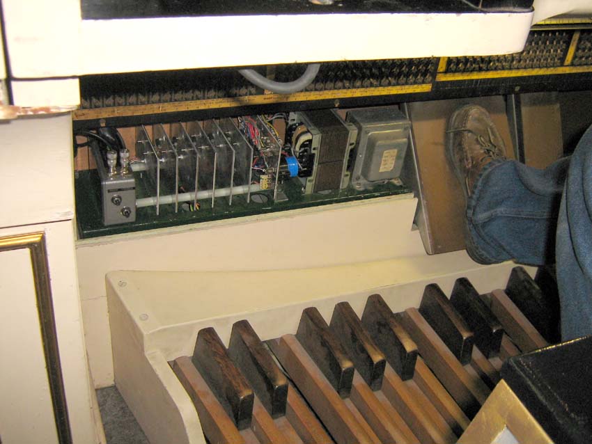
The replacement amplifier in position on the Compton Melotone at the Curzon Cinema, Clevedon
Replacement Amplifier P.A.352
Transistorised version
The replacement amplifier in position on the Compton Melotone at the Curzon Cinema, Clevedon
GENERAL DESCRIPTION
This unit is a combined double pre-amplifier and double power amplifier which is intended as a replacement for the Compton P.A. 352 amplifier in Compton Melotone organs. Two amplifiers are mounted on a common chassis, one handling the bass and the other the treble frequencies. The crossover from one amplifier to the other takes place at about Middle-C (approx 460 c/s).
COMPATIBILITY WITH COMPTON AMPLIFIERS
Inputs
The pre-amplifiers and power amplifiers are electrically interchangeable with the Compton P.A. 352, however, as the original connectors between the generators and the pre-amps are now unobtainable, Belling Lee type 75-ohm television coaxial connectors have been used for the high impedance inputs. Because of this, the original plugs on the leads from the generators will need to be replaced by 75-ohm coaxial types.
Pre-amp Outputs
The gain of the pre-amp is similar to the gain of the P.A. 352 pre-amp; so additional Compton amplifiers may be run from the pre-amp output signals in exactly the same way as if the original amplifier were in use.
Loudspeaker Outputs
Because of the transformerless output stage, this amplifier is only suitable for 15-ohm treble loudspeakers and 6-ohm bass loudspeakers. Unlike the original P.A. 352 power amplifier, this unit can power two loudspeakers in parallel from each output; in many circumstances where two loudspeaker cabinets are needed, this will avoid the necessity to use an additional power amplifier.
Mains supplies
The amplifier is suitable for A.C. mains supplies in the range 200v - 240v. It has a maximum power consumption of approximately 250 watts.
Muting
This unit posseses an additional muting feature which was not present in the original P.A. 352 amplifier. When the mains power is removed, the amplifier promptly mutes itself so that the sound of the generators running down is not audible. The muting facility can also be wired to a remote switch so as to allow it to be manually controlled. In the event of gross overheating of the amplifier (such as may be caused by prolonged operation with short-circuited loudspeaker wiring), the muting circuit operates automatically to protect the amplifier from damage; it automatically resets itself once the temperature has returned to normal.
The colour of the pilot light changes from green to red when muting is in operation.
CONNECTIONS
Input connections are made through 75-ohm Belling Lee type coaxial connectors which must be fitted to the screened cables from the generators. The treble and bass generators must be connected to their correct inputs.
If signals from the pre-amlifiers are required, so as to operate auxilliary power amplifiers, these can be taken from the 'hot' ends of the gain controls which are accessible by removing the cover of the pre-amplifier box. The wiring can be brought out through one of the grommetted holes in the back of the box. Care should be taken to ensure that all the boards are firmly seated in their correct slots before replacing the lid.
The loudspeakers are connected by soldering their leads to the appropriate tags of the fuseholders and earthing points shown in Fig 2.
The power supply transformer will normally be permanently connected to the amplifier, but in the event of having to remove and replace it, the connections are as shown in Fig 3. The centre tap of the transformer must only be connected to the tag provided and not to any other earthed metalwork or tags.
Provision has been made for connection of an external switch to remotely control the muting circuit. The terminals for this are on the opposite side of the panel from the loudspeaker connections. They are normally linked by a yellow wire when external muting is not required. To allow remote muting, remove the yellow wire link and substitute one of the circuits b to d below.
Almost any type of switch will be satisfactory as it only need be capable of switching 24 volts at 10 mA. A spare set of stop tab contacts could be used, provided they are isolated from any other circuit connections.
The manual muting circuit will not prevent operation of the automatic muting system in the event of the amplifier overheating.
Ensure that all fuses are in place and intact before switching on.
CIRCUIT OPERATION
Power Supply (Fig.5.)
A bi-phase 25-volt supply from the mains transformer is full-wave rectified by the bridge of diodes D1 - D4 and smoothed by C1 and C2 to give respectively positive and negative supplies of approximately 30 volts off load. Two slow-blow 6.3-amp fuses, F1 and F2 protect the transformer from excessive current in the event of a fault in any of the circuit components.
Stabilised supplies of + and - 15 volts are derived from the 30v rails by regulators Ic72 and Ic73 which are stabilised against oscillation by capacitors C71 - C74.
Muting (Fig.5.)
An additional 25-volt full-wave rectified supply is derived from the mains transformer by means of diodes D5 and D6. When the muting link is in place (or the remote muting switch, if fitted, is closed) an unsmoothed 100c/s waveform is developed across R71. This waveform is integrated by a time constant of 10mSec formed by R72 and C75 which is sufficient to ensure that the voltage at the inverting input of Ic73a always remains positive, despite a small current drain to the negative rail through R73. Under normal circumstances, the output of Ic73a will remain negative and D77 will prevent Ic73a from having any influence on the thermal sensing circuit surrounding Ic73b. When the mains voltage is removed or the remote muting switch(es) operated to either remove the unsmoothed supply or short-circuit it to earth, the voltage at the inverting input of Ic73a promptly falls below 0 volts and the output of Ic73a switches from -15 volts to + 15 volts.
The thermal sensing circuit uses Ic73b to compare the voltages at the centre points of two potentiometers. One potentiometer consists of R75 and the sensing diodes D71 - D76. When a current of approximately 1.5 mA is fed into the sensing diode network by R75 and R79, the voltage drop across each diode will be approximately 550mV at room temperature, this voltage exhibits a temperature coefficient of -2mV per C°. The six sensing diodes are mounted in intimate thermal contact with the six output transistors of the power amplifiers. Whichever diode happens to be the warmest will have the lowest voltage drop and will determine the voltage drop of the whole parallel network which is applied to the non-inverting terminal of Ic73b. The second potentiometer comprises R76 and R77 + R78 and is arranged to apply approximately 470 mV to the inverting input of Ic73b.
If the voltage drop of any of the sensing diodes falls below 470 mV, which corresponds to a heatsink temperature of around 65°C, the output of Ic73b will switch from the normal running condition of +15 volts to the muting condition of -15 volts. This action also reverses the current flowing through R79 and reduces the voltage drop of the diodes still further, thereby ensuring a positive switching action with a degree of hysteresis. When the temperature of all the sensing diodes falls below approximately 45°C, the action is reversed and the output of Ic73b again switches to the normal running condition.
When the output of Ic73a becomes positive, extra current is injected into R77 & R78 via R74 and D77. This has the effect of raising the voltage at the inverting input of Ic73b to considerably above the sensing diode voltage and forcing Ic73b into the muting condition
Under normal running conditions, the output of Ic73b is at +15 volts and current is applied to the Base-Emitter junction of Tr71 through R81. This allows Tr71 Collector to pass current which switches on the power amplifiers. In the muting condition the Base of Tr71 is driven negative, with D81 preventing excessive reverse bias; Tr71 Collector current can no longer flow and the driver stages of the power amplifiers are deprived of current, thereby muting the amplifiers (see the section on power amplifiers for details).
The pilot lamp, D80, comprises two Light Emitting Diodes in a single package, they are energised by current flowing through R80. The diodes D78 and D79 steer the current through the LEDs so that the green LED is illuminated in the normal running condition and the red LED is illuminated in the muting condition.
Pre-amplifiers (Fig.6.)
These are designed to have similar input impedances, voltage gains and frequency responses to the pre-amplifiers in the Compton P.A.352 which they replace. They are fed from +15V and -15V rails which allows them to deliver output signals up to 25v peak-to-peak without distortion. Any possible noise on the supply rails is reduced by the filters formed by R15 with C9 and R16 with C10. The two circuits are similar, so the Bass circuit will be described and any differences between this and the treble circuit noted later.
The input impedance is determined by the value of R1 which must be high enough that the time constant which it forms with the capacitance of the generators does not fall within the frequency range covered by that bank of generators. It must, however, discriminate against the low frequency charging and discharging transients which occur during the attack and decay of each note. The diodes D7 and D8 prevent excessive positive or negative voltages from reaching the Gate of Tr1; R2 serves to limit the current which can pass through the diodes under fault conditions.
Tr1 converts the input signal voltage to a current signal through the path R4 Tr1 and R7, which is coupled by C3 to Ic1a which acts as a current to voltage converter. Overall the combination of Tr1 and Ic1a acts as a voltage gain block with exceptionally low distortion because the Collector of Ic1a is prevented, by the virtual earth feedback arrangement through R12, from developing a signal voltage swing. The voltage gain of the whole block is set by the ratio of R6 to R7 and is approximately 30 in the bass pre-amp (60 in the treble pre-amp). Stability is ensured by C4 which reduces the loop gain at high frequencies.
The bass pre-amplifier has an additional capacitor, C5, in the feedback loop to reduce gain at higher frequencies. The treble pre-amplifier has a network, C8 and R14, to reduce the output at low frequencies.
Both pre-amplifiers share a common floating earth rail which is connected to the main earthing system by R15. This allows the floating earth rail to take its potential from the earth of the generators, so reducing any hum which might arise due to differences in voltage between the generator earth and the amplifier earth.
The outputs of the pre-amplifiers are applied to R16 and R17 which act as volume controls for the subsequent stages. Connections may conveniently be made to the tags of the variable potentiometers to extract signals from a low impedance source, which are suitable for driving additional external amplifiers.
Bass Power Amplifier (Fig.7.)
Circuit
To handle the output current into two 6-ohm loudspeakers in parallel, the transistorised amplifier uses two paralleled emitter-follower 'totem pole' output stages, each containing two power transistors and two drivers. This arrangement is driven from a voltage amplifier stage which is driven in turn from an input 'long tail pair'. The amplifier is D.C. coupled throughout and a high level of overall voltage feedback ensures low distortion. The gain of the voltage amplifier stage is reduced by C24 at high frequencies to ensure stability. D.C. offsets from the preceding stages are removed by C21 and R22.
Under muted conditions, the power transistors are unbiassed and would be vulnerable to damage from inductively or capacitively coupled interference spikes which might be picked up on the loudspeaker wiring. They are therefore protected from excessive reverse base-emitter voltages by D25 & D26.
Current-limiting protects the output transistors from low impedance faults in the load circuit. Although generous cooling is provided by a separate heat sink for each output transistor, overheating would result from sustained operation into a short circuited load. Thermal protection automatically mutes the amplifier if any heatsink exceeds 65°C, and resets itself when normal temperatures are reached.
The amplifier is designed for optimum operation into one or two parallel-connected 6-ohm loudspeakers. Other impedances can be driven without damage but the efficiency and output power will be lower.
Tr21 & Tr22: Input Long-Tail Pair
The input stage is in the form of a 'long tail pair' which operates by feeding a constant current from Tr23 and R25 into the Emitters of Tr21 and Tr22. Small differences in the Base voltages of these transistors will cause large variations in the current sharing through their Collectors. This arrangement results in very sensitive voltage comparison between the input signal and a proportion of the output signal fed back through R26 and divided in the ratio of R26 to R27. At D,C. the capacitor C22 prevents the dividing action and the entire open-loop gain of the amplifier is available to reduce the output D.C. offset to zero. D21 and D22 prevent excessive Base-Emitter cutoff voltages being developed in the event of a fault.
Tr24, Tr25 & Tr26: Voltage Amplifier and Reference
A constant current flows through the Collector of Tr24 with a magnitude which is determined by its Base voltage relative to the +30-volt rail, held constant by D24, and by the value of R23. D23 compensates for the Base-Emitter voltage drop of Tr24. The current through Tr26 is controlled by the Collector current of Tr38, small variations of which will produce large voltage swings at the Collector of Tr26. Tr25 maintains a potential difference between the Collectors of Tr24 and Tr26 which has a temperature coefficient proportional to a silicon PN junction and acts as a reference voltage to set the quiescent current of the output stages. The normal quiescent current will be in the range 100 to 200 mA and can be checked by measuring the voltages across R37 and R38 (which are mounted on the cooling plates) with an accurate millivoltmeter; the meter should indicate between 22mV and 44mV with no signal.
Tr31 - Tr37: Output Stages
These act in pairs as high current-gain high-power output transistors. Tr30 acts as a comparator between the voltage on its Base and the voltage on its Emitter (which is the same as the voltage on the Collector of Tr31) If the Base voltage of Tr30 rises, Tr30 passes current into the Base-Emitter junction of Tr31 which, in turn, passes a much greater current into R38. When the Emitter of Tr30 has risen in voltage sufficiently to match the rise in its Base voltage, a new set of stable current conditions is established and no further increase in current takes place. The advantage of this arrangement is that the transistors which control the output currents (Tr30, Tr32, Tr34, Tr36) do not handle heavy currents themselves, so their thermally-sensitive operating points are not badly affected by heating. The drift in the operating points of the transistors which become hot because they handle large amounts of power (Tr31, Tr33, Tr35, Tr37) is of no consequence. To ensure that the small voltages which establish the output quiescent current are not affected by differences in the thermal characteristics between Tr30, Tr32, Tr34, Tr36 and the reference transistor Tr25, all five of these transistors are arranged in close thermal contact with a small heatsink which is thermally isolated from the main heatsinks.
Tr28 & Tr29: Current Limiters
The current passed by each pair of output transistors is determined by the voltage between the control transistor and the common rail which joins R37, R38, R39 & R40. By limiting the available drive voltage, this current can also be limited, thereby protecting the output transistors and the load from excessive current. These control voltages, which also appear between the Collectors and Emitters of Tr28 & Tr29, are divided by resistor chains R33, R34 and R35, R36 and applied to the Bases of their respective transistors. When the Base-Emiter voltage of either transistor exceeds 600mV, a Base current flows which draws any further drive current through the Collector to Emitter pathway and away from the output stages. This prevents the control voltage from rising any further and limits the current available from the output stage.
Muting
When Tr71 is switched on under normal operating conditions, the mute line is taken to earth and current flows through R21. This generates a fixed voltage across the zener diode D42 and the thermal compensation diode D23. The capacitor C23 reduces any noise voltages relative to the +30-volt rail. The combined voltage is applied to the Base of Tr24 which supplies a constant current to drive the output stage. The voltage across D24 is applied to the Base of Tr23 through current-limiting resistor R30; this supppies the 'tail' current to Tr38 & Tr39. Under muting conditions, Tr71 ceases to conduct and C23 discharges through R30 and R31 over the course of a few hundred milliseconds, gradually reducing to zero the currents through Tr23 and Tr24. This has the effect of preventing the output stages from being driven either positive or negative, so muting the output.
Fuses
The amplifier output is connected to the loudspeaker(s) through a 6.3 amp slow-blow fuse. Under all normal and most abnormal operating conditions, the fuse will not blow. In the unlikely event of the failure of an output transistor or some other fault which would pass D.C. through the loudspeaker voice coil(s) for a long period of time, the fuse will blow and protect the loudspeaker(s) from destruction.
Treble Power Amplifier (Fig.8.)
This is similar to the bass power amplifier (q.v.) in most respects, however, the following variations may be noted:
Output Load
This amplifier is designed to operate one or two parallel-connected 15-ohm loudspeakers.
Tr23 > Tr53
This is used as a constant current source in a similar manner to Tr24. R25 is therefore unnecessary.
Output Transistors
Because the treble amplifier drives higher impedance loudspeakers than the bass amplifier, it does not need to supply such large currents, so a single set of output transistors is sufficient. Because higher frequencies are being handled, R68 & R70 have been included to give an efficient pathway for the removal of charge from the Base-Emitter junctions of the output transistors.
R28, R33 & R36 > R58, R63 & R66
Values changed to allow for the different quiescent conditions arising from the inclusion of R68 & R70.
C24 > C54
Value reduced to extend the frequency response of the treble amplifier.
C21 > C51
Value reduced to form an additional filter against attack and decay transients.
MECHANICAL CONSTRUCTION
The complete amplifier assembly is constructed on a pair of threaded rods, with nylon spacers which locate and insulate the cooling plates. Each output transistor is in electrical contact with its associated cooling plate, so the cooling plates are 'live' and must not be accidentally connected together by contact with uninsulated wires or metallic objects. The pre-amplifiers and driver circuits, which might be susceptible to electrical interference, are contained within a die-cast metal screening box at one end of the assembly. Power, loudspeaker and muting connections are made to solder tags on a panel at the opposite end of the assembly from the die-cast box.
Dismantling
Access can be gained to the pre-amplifiers and driver stages by removing the cover of the die-cast box which is held by four retaining screws. The circuit boards are retained by slots in the wall of the box and it is important that each board is located in the correct pair of slots (See Fig.9).
To gain access to the output power transistors, proceed as follows:
1) Remove the cover from the die-cast box and carefully pull out the pre-amplifier on its screening plate to give access to the nut which retains one of the assembly rods.
2) Unscrew the nut and screw it onto the opposite end of the rod, on top of the nut which is already there. Tighten those two nuts together to form a locknut.
3) Rotate the locknuts and assembly rod so as to unscrew the rod from the nut which is between the nylon spacers and the die-cast box, holding the nut to prevent unwanted rotation.
4) Withdraw the assembly rod and remove the nylon spacers, carefully noting which way they face, and that that the spacer nearest the loudspeaker connection plate is longer than the others.
5) Slacken the remaining nut on the loudspeaker connection plate a few turns only.
It will now be found that the individual cooling plates can be pivoted on the remaining assembly rod to give access to the power transistors and other components. After replacing a power transistor, ensure that the body of the associated sensing diode is in good thermal contact with the transistor retaining screw head and well covered with thermal transfer compound.
When reassembling the amplifiers, proceed as follows:
6) Return the cooling plates to their correct positions and, from the loudspeaker connection plate end, insert the assembly rod by increments. Place each nylon spacer into its correct position as the rod is advanced (the longest spacer will be the first to be positioned). The spigot of each spacer faces towards the loudspeaker connection plate end of the assembly.
7) When the rod reaches the outside of the die cast box, position a nut between the last spacer and the outside of the box, then screw the rod through the nut and into the box. Continue screwing the rod until it projects inside the box by no more than the thickness of a nut.
8) Undo the locknut assembly and return one of the nuts to the end of the rod inside of the box. Firmly tighten this nut against the box wall and outer nut.
9) Insert the screening plate of the pre-amplifier into slot 20 and carefully return the pre-amplifier board to its correct position. Ensure that no wires are trapped and replace the box lid.
10) Evenly and gently tighten both nuts at the loudspeaker connection plate end of the assembly until all the cooling plates are just held firmly in position.
SPECIFICATION
Supply voltage .. .. .. .. 240v A.C.
Supply frequency .. .. .. 40 - 60 c/s
Power consumption .. .. .. Less than 250 watts
Input impedance - Bass .. .. 2.2 Megohms
Input impedance - Treble .. .. 470 kilohms
Normal input signal .. .. .. 5mV RMS
Maximum input signal .. .. .. 150mV RMS
Frequency response - Bass .. .. 20c/s - 1Kc/s +-3dB
Frequency response - Treble .. 300c/s - 23Kc/s +-3dB
Output power - Bass .. .. .. 45 Watts into 6‡
90 Watts into 3‡
Output power - Treble .. .. 15 Watts into 15‡
30 Watts into 7.5‡