The Mullard "Orgola III"of 1931

Original advertisement

,

 Brown Bros page of adverts

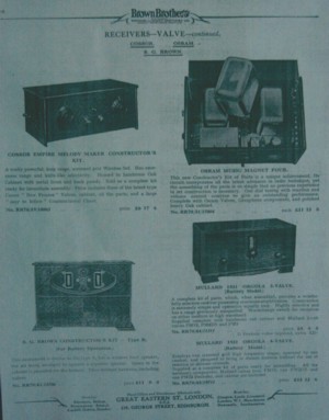
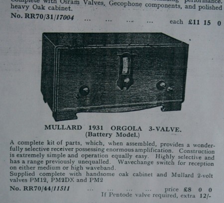
 Orgola III Advert (bottom right adjacent.)

Mullard issued several versions of the "Orgola" set during the late 1920`s and early 1930`s

In this case the set was acquired from Philip Knighton of Wellington (gramman@msn.com). The documents were sought later and supplied by Savoy Hill Publications (savoyhill@lineone.net.) The set is the more expensive version at 12/- (twelve shillings) extra to include an output pentode.This also must have resulted in the addition of a 5k resistor and associated decoupling condenser,not shown on the "point to point" diagram.

Note the price in the advert at £8 0 0. This was at a time when working men were earning around £4 a week. Convert that into today`s money.


 It was not apparently the practice to supply a theoretical circuit diagram; seems they did not have much confidence in their customers technical knowledge.

The adjacent circuit has been produced from the "point to point" one. It shows the minimal circuitry and the inclusion of a 5k Ferranti resistor and associated 2mfd condenser not shown on the "point to point".

 The original "Point to Point" wiring diagram, with detailed instructions on the right hand side  


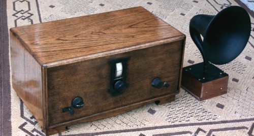
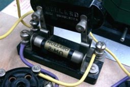
 It was a gem of a find, having on it`s baseboard the guarantee of it`s provenance


It was complete in it`s original oak cabinet. Internally the whole looked intact if rather scruffy. In theory it could have just been coupled up and switched on; but examination revealed an open circuit manually adjustable aerial coupling coil and all decoupling condensers "conductive".Although dated 1931 the technology was sometimes more late 1920`s, viz:

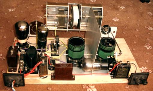
 The grid condenser of the detector valve is a "plug in" item to the 2 megohm grid leak


 The rheostat in the filament lead of the Screen Grid valve; it acted as a quite effective volume control.


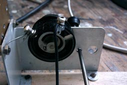
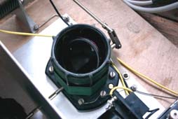
 The bellcrank lever for wavechanging.The manually adjustable aerial coupling coil can be seen inside the main coilformer.


 The tuning coils were by Colvern, the tuning condenser arrangements by Jackson Bros; valves (Screen Grid-PM12, Detector-PM2DX, Output-"Pentone"-PM22) and intervalve transformer by Mullard and the single fat wirewound resistor by Ferranti.


The original amateur wiring using uninsulated wire was so awful and liable to short circuit that it was rewired, keeping to the original point to point connections.It would appear the original constructor only had to woodscrew the supplied components into the marked holes and copy the full size point to point wiring diagram and the set would be complete.No knowledge of "Wireless" would be necessary - a real "screwdriver and pliers " job.

Restoration:

The horn of the horn loudspeaker is genuine vintage,it`s base unit not so, they are expensive things to buy in working order. It has been said that the horn loudspeaker era predates 1931 and so it not really appropriate. However, since some of the original circuitry also seems to predate 1931 perhaps this can be excused.

The restored interior


Return to Homepage