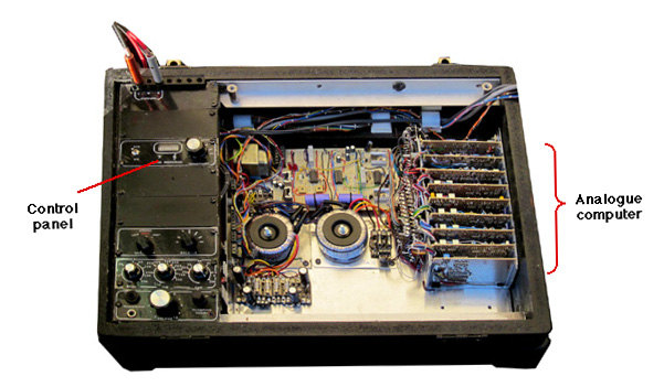
ARCHIVAL RECORD PLAYER WITH DECK REMOVED TO SHOW ANALOGUE DE-CLICKING COMPUTER
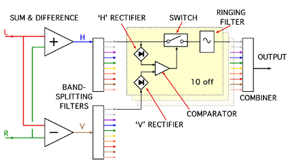
BLOCK DIAGRAM
ANALOGUE COMPUTER FOR DE-CLICKING
Link to parallel-tracking
turntable
Block diagram
Power supply
Sum & difference input amplifiers
Band-splitting filters
Signal rectifiers
Switching
Ringing filters
Combiner
Threshold generator
ARCHIVAL RECORD PLAYER WITH DECK REMOVED TO SHOW ANALOGUE DE-CLICKING COMPUTER
BLOCK DIAGRAM
The Left and Right signals from the pre-amplifier are added to give the horizontal signal (H) and subtracted to give the vertical signal (V). The Horizontal signal contain the wanted sound plus noise (clicks, crackles etc), the Vertical signal contains only the noise.
The Vertical and Horizontal signals are each split into octave bands by filters. Each pair of bands is compared and, if the absolute amplitude (full-wave rectified voltage) of the Vertical signal is more than a certain percentage of the absolute value of the Horizontal signal, this indicates diagonal stylus movement corresponding to scratch or crackle.
If a click is detected by the comparator, a switch is opened, interrupting the signal path for the duration of the click. The filter follwing the switch continues ringing with approximately the frequency, amplitude and phase of the missing portion of the waveform until the switch recloses and normal operation is resumed. Unwanted harmonics and intermodulation products from the switching process lie outside the bandwitdth of the ringing filter and are attenuated.
The outputs from the ringing filters are recombined to regenerate the original signal without the clicks. Because the band-splitting filters and the ringing filters give complimentary outputs, the signals can be recombined without phase anomalies at the crossover points, so the original waveform is accurately reconstituted.
POWER SUPPLY +
SUM & DIFFERENCE AMPLIFIERS
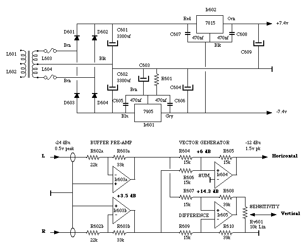
Because CMOS switches are used in later stages, it is important that the overall power supply is limited to 15v. Any signals that exceed the power supply voltage could cause latch-up of the CMOS circuit, so all the signal amplifiers must be fed from the same supplies. The gain of the vertical channel is higher than that of the horizontal channel to allow for some attenuation in the SENSITIVITY control.
BAND-SPLITTING FILTERS
(Each an octave wide)
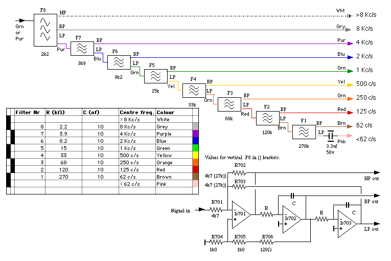
RECTIFIERS, SWITCH & RINGING FILTER
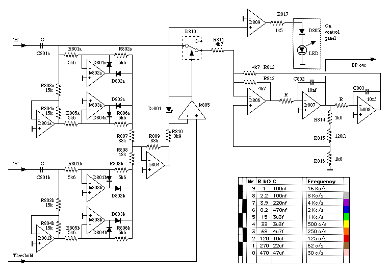
Comparator gain is greater for the Vertical channal to make the circuit more senstive to near-horizontal vector movement, which can be the cause of noise in some pressings or in cases of a distorted groove cross-section for which no suitable stylus is available.
COMBINER & THRESHOLD SIGNAL GENERATOR

The signals from the ringing filters are recombined with equal weighting to give the output signal.
At high slew-rates the discrepancy between the original cutter tip and the replay stylus can generate spurious vertical movement; this is known as the 'pinch effect'. If this is allowed to trigger the switching action of the de-clicker it can generate distortion of the output signal. To prevent this, the detection threshold of the comparator is raised at high slew rates by a voltage generated by differentiating the output signal.
Because the de-clicker works by comparing the signals picked up from the two groove walls, any phase error between those signals can generate a spurious response. To eliminate the phase errors which arise from a pivoting pickup arm, this system requires a parallel-tracking arm.
Link to parallel-tracking turntable